Several operational variables must be considered when choosing an API 682 piping plan for dual pressurized seals. These variables include flow rate, heat load, normal operating pressure, the number of mechanical seals to be serviced, and available utility requirements. Each seal support system will have advantages and disadvantages in relation to the variable operating conditions of API 682 Plan 53B and Plan 54 piping plans. Each application should be evaluated on a case-by-case basis for mechanical seal longevity and reliability.
Plan 53B system
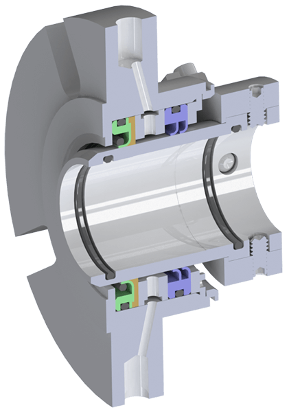
A Plan 53B system utilizes a bladder accumulator to provide a typical operating pressure of 30- 50 psi above maximum seal chamber pressure when servicing one mechanical seal per system. The bladder accumulator prevents gas entrainment for operating pressures above 200 psi. The bladder is pre-charged with nitrogen using a charging kit and Schrader valve (like a car tire) and creates a separation between the nitrogen source and seal support barrier fluid. As a mechanical seal leaks barrier fluid into the process fluid, the operating pressure will drop until an alarm signals personnel to refill the unit until normal operating barrier pressure is returned. A refill period of 20 – 30 days is targeted and is based on bladder accumulator size (5, 10, or 15 gallons), seal leakage, and normal operating pressure.
The term usable fluid is referenced when sizing bladder accumulators. The available usable fluid is dependent on normal operating pressure. The higher the operating pressure the less usable fluid is available. A Plan 53B with a 10-gallon bladder accumulator operating at 100 psi will have more usable fluid than the same system operating at 500 psi. Note for pre-charging the bladder: the maximum barrier pressure must be less than 4 times the pre-charge pressure (Pb1max < 4 · P0) and the bladder pre-charge pressure must be 90% of the minimum barrier pressure allowable.
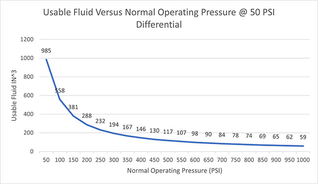
Higher barrier pressure differential operating pressures above maximum seal chamber pressure will increase available usable fluid. Specifications requiring an increase from 50 to 100 psi above maximum seal chamber pressure will result in an increased time period before re-filling, assuming the usable fluid increase is not exceeded by an increase in seal leakage. However, the higher seal face leakage and increased heat generation which may occur at a higher barrier pressure differential must be accounted for in the mechanical seal / seal support design. Barrier differential pressures above 100 psi over maximum seal chamber pressure are not recommended due to diminishing returns between heat generation and increased leakage rates.
Plan 53B systems have an estimated maximum heat removal rate of 8,000 – 12,000 BTU/HR for target barrier fluid supply temperatures of 120°F. As heat removal rates exceed 12,000 BTU/HR, target temperatures and other seal support piping plans can be evaluated on a case-by-case basis.
Other factors to consider are flow rate and fluid circulation: either can be achieved by utilizing a pumping ring or an external gear pump. Pumping designs without pumping rings will require an external mag-driven positive displacement gear pump with typical flow rates of 1 to 3 GPM and can be less cost effective when compared to a Plan 54. A Plan 53B with an external gear pump is a closed loop system requiring the external pump to have the same pressure on suction as discharge. Appropriately-sized entry glands to and from the seal as well as the limited use of elbows should be utilized to prevent a differential pressure of 75 psi maximum between the lubricator pump suction and discharge, otherwise the lubricator pump can decouple. A Plan 54 is an open loop system with an atmospheric tank and filler/breather. Depending on the main pumping process, a Plan 53B closed loop system may be optimal for containment purposes with respect to environmental health and safety concerns in the event of a system upset.
In Summary, the determining criteria for selecting a Plan 53B includes:
- Barrier Pressures > 200 psi.
- Prevents gas entrainment.
- Usable fluid acceptable for available maintenance for refill rate.
- Heat load removal will not exceed Plan 53B removal capacity of > ~ 12,000 BTU/HR.
- Main process pumping temperature < 500°F.
- Pump design includes a pumping ring for circulation.
- Environmental health and safety concerns require closed loop for process containment.
- One Plan 53B system per mechanical seal is acceptable.
API 682 Plan 54
An API 682 Plan 54 is available for those applications where operating capabilities such as flow rates, heat load requirements, normal operating pressures, and seal-per-system limitations exceed acceptable Plan 53B guidelines. The Plan 54’s normal operating pressure remains constant in relation to seal leakage unlike a Plan 53B where normal operating pressure decreases with leakage.
One Plan 54 can service one or multiple mechanical seals. When multiple systems are serviced by one Plan 54, all these systems must be evaluated for critical operation in the event of system failure. If deemed necessary, a redundancy plan to prevent system failure can be included in the design. Redundancy equipment can include primary and back up lubricator pumps, duplex filter assemblies, and dual heat exchangers. Multiple mechanical seals can be isolated and serviced without shut down, allowing other equipment to remain online and operational. A secondary power supply – when available – is recommended for a backup pump motor in event of main power disruption.
The Plan 54 holds a specific advantage over Plans 53 A/B/C because location proximity to the main pump is not required. In addition, Plan 54 selection is driven by shaft speed, circulation device limitations, and heat load. These specifications differ from the Plan 53 series’ required circulation rate which relies on size, circulation device, and piping to cool and lubricate mechanical seals.
Barrier fluid must be compatible with the main process. Typical barrier fluids include water, a 50/50 mix of ethylene glycol and water, and mineral or synthetic oils. Vane pumps using water as barrier fluid are limited to a normal operating 150-170 psi. The use of oils as barrier fluid provide further lubricity and normally operate in pressure ranges of 100 – 1000 psi using modulating back pressure control valves; higher normal operating pressures are contingent on this back pressure control valve design.
A Plan 54 operates 30 – 50 psi above maximum seal chamber pressure and remains constant. For seal chamber pressure fluctuations, plan equipment can include digital pressure tracking control to maintain a 30 – 50 psi bias versus using constant pressure regulators. A pressure transmitter on the seal chamber references a pressure transmitter on the Plan 54 system to maintain a bias through DCS. Alternatively, using a pressure tracking mechanical valve with a reference line to seal chamber can maintain bias through mechanical means.
Positive displacement gear pumps with heat exchangers are designed for large amounts of heat removal – think high speed, high pressure, and large equipment for Plan 54 applications. Cooler types include water cooled shell and tube and forced air cooled driven by an electric motor. Each cooler type is sized to deliver 120°F barrier fluid supply. Both utility sources – electric power and cooling water – must be readily available. A temperature control valve can be included to maintain the desired supply temperatures.
Simplex or duplex filter assembly options are included. Duplex filter assemblies allow elements to be changed while unit is running and operational. Differential pressure instrumentation is included for monitoring element condition and signaling when the element should be replaced. Filter assemblies can be upstream or downstream of the mechanical seal. Typical arrangement downstream is under atmospheric conditions. Placement on supply is required to meet the pump protection valve setting.
Transmitters or mechanical switch instrumentation is offered for equipment monitoring. Alarm logic for level, pressure, flow, and temperature is typical. Considerations for alarm logic is based on system complexity or the number of seals on the system.
Lastly, a Plan 54 can be equipped with a bladder accumulator safety package. Located upstream, the package includes a bladder accumulator and check valve on supply. The downstream package includes a normally closed solenoid or actuating ball valve on return. The solenoid can receive a signal to fail closed, maintaining a positive pressure for short periods of time which may be hours or days depending on seal leakage rate. This prevents reverse pressurization during upset and allows time for trouble shooting.
In Summary, the determining criteria for selecting a Plan 54 includes:
- Main process pumping temperature >500°F and < 800°F.
- Barrier pressure operating > 200 psi.
- Main pump process constraints include zero-emissions, hazardous materials, poor lubricity.
- 100% Barrier pressurization requirement.
- Unavailable space for proper Plan 53 piping plan installation.
- Barrier fluid circulation rate beyond pumping ring capability.
- Refilling period of reservoir during recommended routine maintenance every six months
- One Plan 54 can service multiple mechanical seals.